OVERALL INDEX----> [ WILD THING PART1 ] [ WILD THING PART2 ] [ WILD THING PART3 ] [ WILD THING PART4 ]
Part 3 index ---> [LEG DRIVE] [ARM DRIVE] [WHEELS, GEARS, AND BRAKES] [SEAT]
I chose a standard circular motion for the leg drive system, primarily to simplify the work involved. The use of standard cranks, pedals, and bearings minimized the cost and machine time necessary to produce a working prototype. Also, my legs already know how to provide power going in a circle and any other motion (e.g. linear) might make an already different riding experience even more challenging to master. The crank axis, or bottom bracket, is attached via a clamp arrangement to the front part of the backbone tube Figure P9 allowing an adjustment for different rider leg lengths {alas, it hasn't been moved since I first cinched it down}. The backbone tube is chrome plated in this section so that there is no paint to mar as an adjustment is made {money down the drain}.
As described in the steering section of this report, the of the arm drive is a linear push and pull roughly parallel to the rider's spine. Instead of a purely linear motion, I decided to use a pair of levers that move back and forth through approximately 45 degrees of arc. This yields a pseudo-linear motion for the hands, is compatible with the steering system, and allows the use of simple pulleys on the inside of the arm drive lever bearing housings (Part I in Figure 2, {Back on Part 1} and Part A in Fig 4 below.)

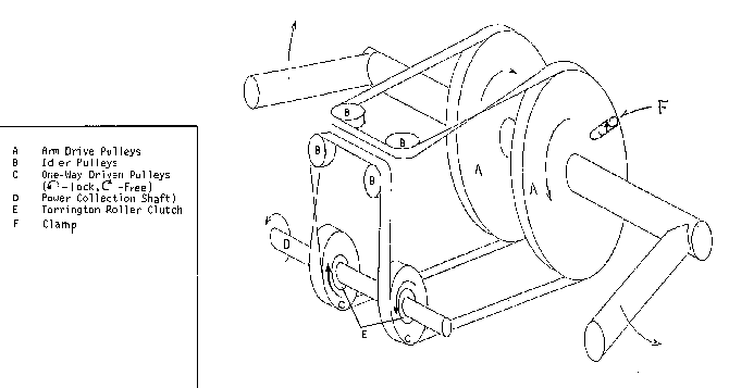
Since the Wild Thing is intended primarily to provide exercise and utilize as many of the body's muscles as possible, the arm drive system was designed to extract work from both pushing and pulling the levers. Conventional rowing machines use the pulling muscles only. Figure 4, Figure P7, and Figure P8 Illustrate how this is accomplished. A single belt make of plastic strapping material similar to that used in the steering mechanism is strung over 8" diameter pulleys "A", idler pulleys "B", and 2" diameter driven pulleys "C" mounted on the central power collection shaft via Torrington roller clutches "E". The arm levers are thereby constrained to move in opposite directions, and, depending on which lever is being pulled, one or the other driven pulleys drives the shaft. The other driven pulley spins freely. Both pulleys spin freely if the arm levers are not stroked. The Wild Thing can be ridden with foot power and no arm power, but not vice-versa. { Figure 4 is oversimplified in that it appears that there is only one layer of tape, and that drive is accomplished through friction at the Driven Pulleys. In fact, there are two lengths of tape. The ends of one length are inserted into radial slots on the driven pulleys after wrapping around them a couple of times (c-f-b-b-f-c). Without this feature, the tape would just slide over the pulley. The other length is used to keep tension on the whole affair (f-c-b-b-c-f).}
The one- way bearings, or roller clutches, are rated for a torque carrying capacity of 412 in-lbs. Given the diameters of the pulleys and the 12 inch length of the arm levers. A rider would have to push and pull each lever with a force of 68 lb., or exert a force of 136 lb. between them to exceed this rating. Since the strap is rated at 300 pounds it could break if the rider exerted as much as 100 pounds between the levers. If the rider were capable of exerting this much force while cycling the levers through an eight inch arc at a rate of one cycle per second, he or she would be generating .25 horsepower, which is certainly more than I am capable of sustaining for very long. {The arm drive proved very reliable. The only thing I would do different would be to make the idler pulleys "B" a larger diameter, say 2". Eventually the tapes delaminate, due to the bending cycles they experience going over the small pulleys.}
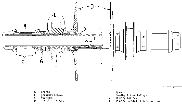
The power collection shaft (PCS) is so named because it not only receives power from the one-way pulleys but form the leg cranks as well. Two sprockets are affixed to the PCS: one connected to the crank by a chain, the other to the rear wheel. The PCS structure is shown in Figure 5 below.

The PCS is composed of two Columbus steering tubes "A", joined by a sleeve "B" and running in standard bicycle headset bearings "C". {The bearings were a poor choice, because they required exact alignment of the two bearing housings during frame construction. I managed it, but was glad I only had to make one! Ball or needle bearings would have been better, but I was fixated on the use of standard bike-store parts.}
Columbus steering tubes were used because they already had threads on one end for the bearing adjuster nuts and come with an accurately ground, one-inch diameter. The sleeve was machined out of mild steel and the spiders "D" that hold the sprockets were turned from aluminum plate and shrunk onto the sleeve. The spacers "E" on either side of the one-way driven pulleys "F" are turned from Teflon and take up any axial loads. The bearing collars "G" are mild steel and clamp into a groove on "A" with set screws to fix the inner bearing cones. "A" has been hard-chrome plated on the surfaces where the roller clutches ride to extend their life and assure the rated capacity of the mechanism. Extra care was taken during frame construction to see that the two PCS bearing housings "H" were on the same line so that the bearings would run freely. {and you know why!}
The Wild Thing's wheels are make from standard 27" x 1 1/4" tires mounted on aluminum rims. The rear hub is a Sachs Orbit, a unit that combines a five-speed freewheel with a two-speed internal gear and an integrated drum brake. The Wild Thing therefore has ten speeds shifted from levers on the front of the seat and a rear drum brake activated by a lever on the left arm lever. The front hub is currently an old Normandy Competition directly out of a dumpster, although a drum brake hub is planned. {A Sachs front drum hub did go on the front, and would be fine except for the fact that the long cable is too stretchy. A hydraulic caliper brake would be the ticket nowadays}
The seat (Figure P10) began as a beach chair attached to the frame with strapping tape. It evolved through a process of subtraction until it was low enough to allow the rider to touch the ground and narrow enough to allow his/her arms to perform the necessary driving and steering motions. The backrest was make adjustable with brackets made of 1/8" aluminum plate and extended upwards with an old backpack frame to support the rider's back. The Wild Thing is quite comfortable, and feels much like a La-Z-Boy recliner (Figure P1)
END OF PART 3
OVERALL INDEX ----> [ WILD THING PART1 ] [ WILD THING PART2 ] [ WILD THING PART3 ] [ WILD THING PART4 ]